fbpx

Advanced Layer Tools

Advanced Layer Tools

CMS IntelliCAD® 8 now provides advanced layer management commands and toolbars.

There are a variety of new layer management enhancements in IntelliCAD 8.x: Layer States, Layer Filters, Layer Search Control (Layer Explorer), New Layer Properties in Explorer (Transparency, New VP Freeze), New Layer Tools Toolbar and New Layer Tools Menu. Layers in CMS IntelliCAD are like the transparent overlays you use in manual drafting.
User can use layers to organize different types of drawing information. In IntelliCAD, each entity in a drawing exists on a layer. When users draw an entity, it is created on the current layer.

Uers can control the visibility of layers in individual viewports. When turning a layer off, entities drawn on that layer are no longer visible, and they do not print. Although a layer may be invisible, you can still select it as the current layer, in which case new entities are also invisible until the layer is turned back on. Entities on invisible layers can also affect the display and printing of entities on other layers. For example, entities on invisible layers can hide other entities when using the Hide command to remove hidden lines.

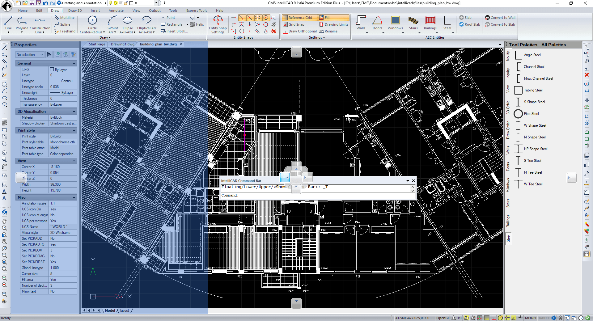
Users have several available simultaneous options to access Layer tools. CMS IntelliCAD Menu, Ribbon tools and Layer toolbar are all available at the user interface.

Ribbon Layer Tools Layer Toolbar

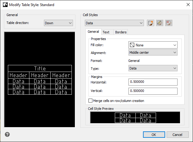
Some drawings contain large lists of layers, in which case you can search for layers by name, or you can organize layers into subsets using layer filters. Layer states are also useful for drawings that contain many layers. With layer states, you can assign properties to individual layers and save them in a layer state, then apply those settings at any time.

BIM support - IFC, *.rvt & *.rfa

BIM support - IFC, *.rvt & *.rfa

Building Information Modeling (BIM) support in CMS IntelliCAD®

CMS IntelliCAD® PE Plus edition now fully supports BIM import/attach IFC files and Autodesk® Revit® files as underlays, based on the ODA BIM component.

Interchange Building model data is becoming an increasing reality between collaborative corporations and organizations. CMS IntelliCAD® PE Plus provides such support from 9.0 version.

Printing and Publishing

Printing and Publishing

IntelliCAD Print Settings

With CMS IntelliCAD® users can print a copy of user drawing exactly as created, or users can add formatting and specify print controls to change how drawings look when it printed.

Sometimes users may require multiple printed drawings, each with a different look or layout. For example, it may be needed one printed drawing for a client presentation, along with several other variations for production contractors. For each type of printed drawing that users require, they can create a layout that defines its characteristics, including scale, area to print, print style tables, and more.

Publishing drawings

Rather than print one drawing at a time, users can use the Publish command to save and print a collection of drawings and their layouts. First, by creating a sheet list by specifying the desired layouts, which can be a combination of model space and paper space layouts from any drawing. Secondly, saving the sheet list and then printing it.

Additionally, starting from CMS IntelliCAD 8.3, publishing now also features eTransmit command. This command collects related files and packages them together for transfer to another computer. Packages can include one or more drawings and their related external references and fonts. Each package can be either a self-extracting .exe file, a .zip file, or a new folder that contains all of the files.

eTransmit Publishing eTransmit UI

Multi-language Support

Multi-language Support

Multi-language support in CMS IntelliCAD®

CMS IntelliCAD English user interface

CMS IntelliCAD simplified Chinese user interface

CMS IntelliCAD German user interface

CMS IntelliCAD Spanish user interface

CMS IntelliCAD French user interface

CMS IntelliCAD® user interface is translated and supports several languages. Currently it supports* English, Simplified Chinese (zh-Hans), Traditional Chinese (zh-Hant), Czech - CS, Dutch - NL, French - FR, German - DE, Italian - IT, Korean - KR, Polish - PL, Portuguese - PT, Russian - RU, Spanish - ES. (*) Some not yet fully supported.

Spanish, French, and Portuguese interfaces now translated even better in CMS IntelliCAD 12.1!

Instructions on how to setup the language interface are available HERE

Tables Editing

Tables Editing

CMS IntelliCAD® 10.1 Now supports tables creation & editing

CMS IntelliCAD tables support

Starting from CMS IntelliCAD® 10.1, it's now possible to create & edit tables and also table styles. Users can insert or delete lines or columns, and stretch cells size or table using its grips points

CMS IntelliCAD tables styles manager

Starting from CMS IntelliCAD® 10.1, it's now possible to create & edit tables and also table styles. At Tables styles it's possible to setup the text fonts at the table title, header or data cells. Users can also insert or delete lines or columns, and stretch cells size or table using its grips points

ACIS 3D, Solids and 3D modeling

ACIS 3D, Solids and 3D modeling

3D modeling, Solids Modeling and ACIS .SAT file support in CMS IntelliCAD®

CMS IntelliCAD® PE Plus edition fully supports Spatial® ACIS solids modeling. Autodesk .dwg 3D solid modeling is compatible with ACIS file format. This means that 3D drawings created with CMS IntelliCAD® or AutoCAD®. CMS IntelliCAD® includes a non-history based, non-parametric-associative and non-direct modeling solids modeler. By being so, it's extremely fast to handle thousands of 3D individual solids entities with CMS IntelliCAD® resulting on a amazing graphics performance experience while handling large 3D files.

Interchange CAD data is a requirement and a reality between collaborative corporations. CMS IntelliCAD® PE Plus is able to import, edit, and export any existing .sat file files up to version 23 allowing 3D entities data interchangeability with other 3D CAD packages like SolidWorks®, Inventor, Alibre® or SolidEdge®.

CMS IntelliCAD PE is able to create 3D surfaces and meshes.

Starting from CMS IntelliCAD® v8.2 PE and above, it's now possible to import *.sat files in to IntelliCAD model view through ACISIN command. Additionally, though not being able to create/edit 3D solid entities, it also supports *.dwg file viewing that include such CAD entities.

CMS IntelliCAD® v9.0 PE and above include the ability to draw and modify 3D meshes using the new Facet Modeler for lightweight 3D drawings.

STEP, IGES Import & Export

STEP, IGES Import & Export

STEP, IGES Import & Export in CMS IntelliCAD® 9.2 and following

CMS IntelliCAD 3D STEP file import as solid object

CMS IntelliCAD® 9.2 now extends even more interoperability by supporting the ability to import STEP (.ste, .stp, .step) and IGES (.igs, .iges) file formats. Users will be then able to edit solids or surfaces geometry and then export them back as ACIS .sat, STEP .step or IGES .igs

Command Line, Menus, Toolbars and Properties Pane

Command Line, Menus, Toolbars and Properties Pane

CMS IntelliCAD® supports hundreds of AutoCAD® software commands. Select AutoCAD® software commands from the pull-down menus and toolbar icons, or type AutoCAD® software command syntax at the optional command line prompt - whichever best fits your work style. You can work with the CMS IntelliCAD window and its elements in a variety of ways. For example, you can display and rearrange the toolbars, display the command bar, and enable the status bar. The toolbars and command bar can also be floated anywhere on the screen or docked to the edges of the main IntelliCAD window.

The command bar is a dockable window in which you type IntelliCAD commands and view prompts and other program messages. By default the command bar displays the three most recent lines of prompts, but you can extend the window to display more lines. Move or resize the command bar by dragging it.

CMS IntelliCAD® also supports AutoCAD® software menus (MNU), dialog boxes (DCL), fonts (SHX), scripts (SCR), and symbol libraries, so you can easily transfer custom AutoCAD® software environments into IntelliCAD® and continue working in your favorite drafting environment.

When you type in the command bar, IntelliCAD suggests names of matching commands as you type. The suggested names appear in an AutoComplete window. Simply select the desired command in the list. In addition to command names, suggestions can include names of external commands, system variables, aliases, and LISP functions.

Commands can also be deployed from the IntelliCAD dropdown menu by choosing them from the available list of menu options. The available menu options depend on the experience level that is set at the IntelliCAD general options. Users can use both the default Ribbon interface and the IntelliCAD dropdown menu. IntelliCAD menu bar is not available by default and can easily be activate through a right mouse click on top of the IntelliCAD Ribbons.

In the Properties pane, changes that you make in the Layer, Color, Thickness, Lineweight, Linetype, Linetype Scale, and Print Style (if using named print style tables) fields affect all selected entities. To change the properties of a single entity in the selection set, choose the entity from the list at the top of the Properties pane. You can select the entities to be changed using any entity-selection method.

Importing and exporting customization files

You can continue using aliases and menu files from AutoCAD by importing the appropriate file. You can import AutoCAD customization files and export IntelliCAD formats using the Customize dialog box. All of the files listed in the following table are in ASCII format, which means you can view and edit them with a text editor, such as Notepad.

Importing custom .pgp  .cui, .mnu

PDF import to .dwg

PDF import to .dwg

Understanding PDF import to .dwg using CMS IntelliCAD® 9.2 Premium Edition

CMS IntelliCAD .PDF file import to .dwg

Updated CMS IntelliCAD® PE and PE Plus interoperability features also now support vectored .PDF file import through the IMPORT feature.

Vectored objects, including text objects, are typically imported and converted in to IntelliCAD as polylines, lines or splines. Non vectored, or raster objects, are not imported.

Native *.dwg and *.dgn support

Native *.dwg and *.dgn support

Native .DWG file support - from version 2.5 to 2018/20

CMS IntelliCAD fully supports AutoCAD legacy drawings. IntelliCAD reads and writes .dwg files in their native format without any loss of data, from AutoCAD 2018 back to Version 11, including AutoCAD LT®. Because IntelliCAD uses Autodesk DWG compatible file format as its native file format, no translation is required.

CMS IntelliCAD® opens, edits, and saves any existing .dwg file files saved in version 2.5 through 2018, without conversion or data loss. That makes CMS IntelliCAD® 9.x more compatible with older versions of AutoCAD® software than AutoCAD® software itself!

Plus, starting from CMS IntelliCAD v8.2, it's now possible to natively OPEN and EDIT *.DGN files. *.DGN files will be saved natively as *.DWG files.


As CMS IntelliCAD is able to import DXF, DXB, DWF, DWT and DAE format files, it can also open MicroStation *.DGN format files by converting them to .dwg files.

Open .dgn file using CMS IntelliCAD

Additionally, CMS IntelliCAD is now also able to export cad file as MicroStation *.DGN file format using the EXPORT command.

CMS IntelliCAD .dgn export

Page 2 of 5